
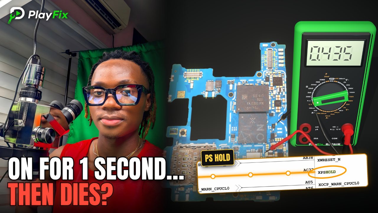
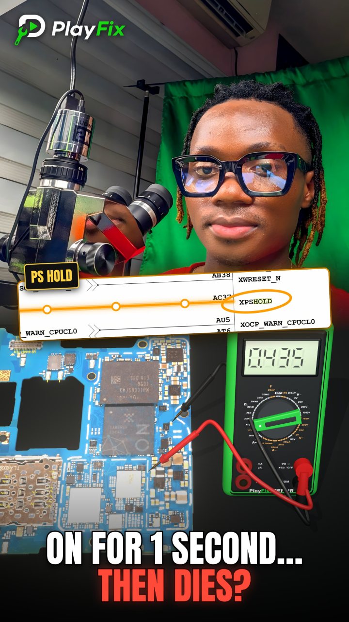
PS Hold Signal Line Explanation and PMU Troubleshooting
1:01 · Phone repair course basics and circuit theory
Knowing how a phone powers on is the foundation of fast diagnosis: the battery and VPH, the power management IC, the main supply rails, the PS_HOLD signal and the CPU/RAM handshake. Block diagrams and schematics turn guessing into a step-by-step test plan.
Every phone follows a similar power-on sequence: the battery feeds VPH (VDD_MAIN), the power key wakes the power management IC, the PMIC creates the supply rails for the CPU, RAM and storage, and the CPU confirms a good start by holding the PS_HOLD signal.
Block diagrams show that sequence for a specific phone, and schematics show the exact components and test points. Learning to read them is what separates part swapping from real board-level diagnosis.
1:01 · Phone repair course basics and circuit theory

3:05 · Phone repair course basics and circuit theory
1:46 · Phone repair course basics and circuit theory
1:46 · Dead phone repair (no power, no boot)
4:51 · Phone not charging repair

1:11 · No SIM card and network repair
0:44 · Phone repair course basics and circuit theory
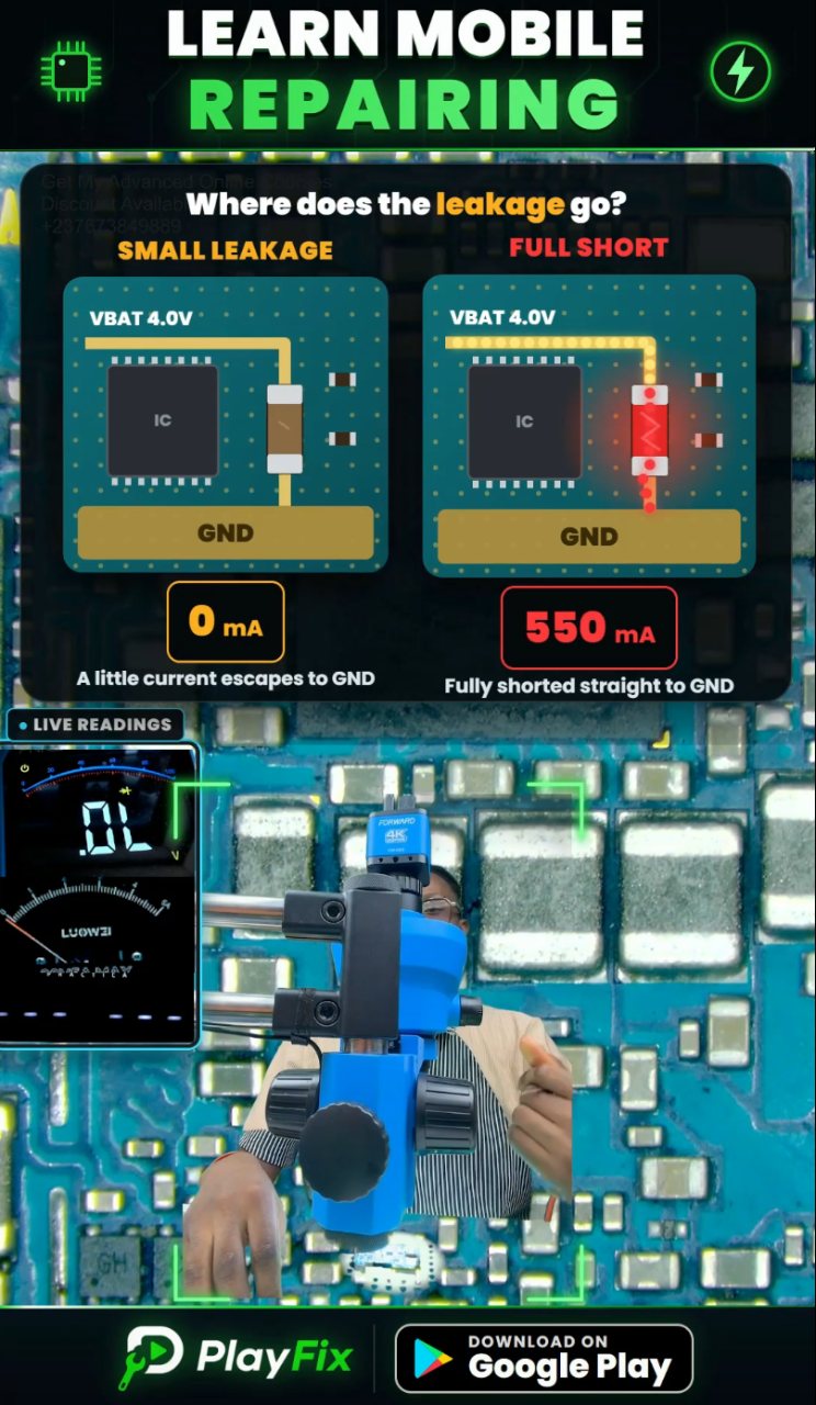
3:42 · Dead phone repair (no power, no boot)

0:53 · Phone repair course basics and circuit theory
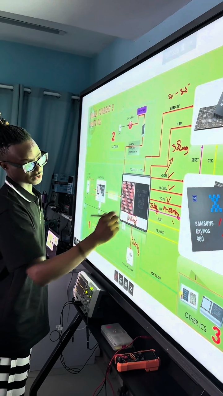
0:59 · Phone repair course basics and circuit theory
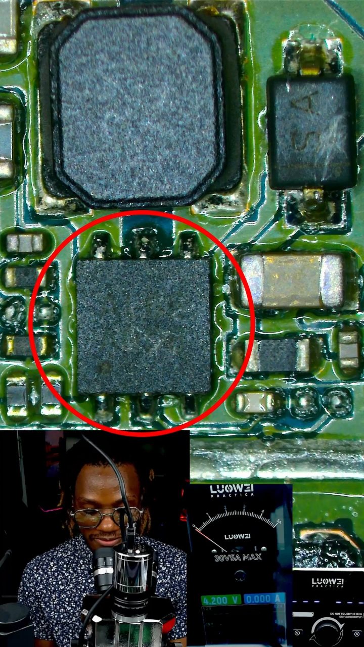
4:13 · No display and backlight repair
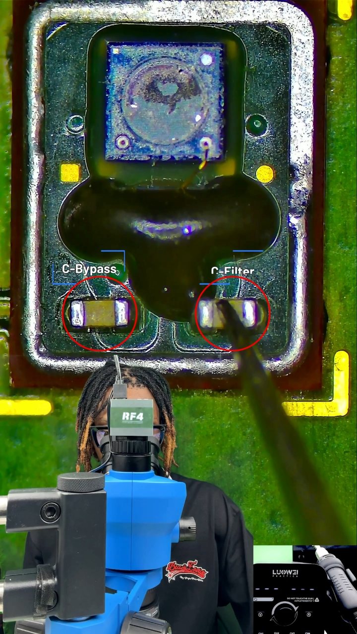
0:42 · Phone repair course basics and circuit theory
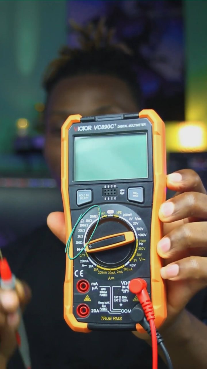
8:39 · Phone repair course basics and circuit theory
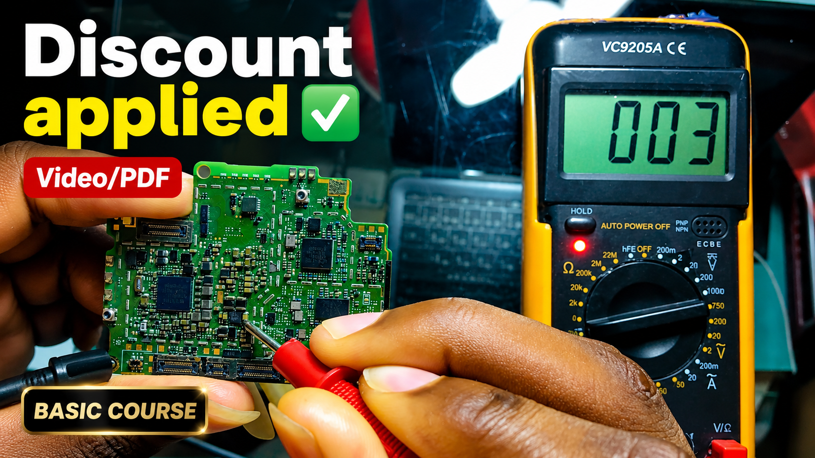
English repair videos with English and French PDF learning materials.

Advanced English video training for professional mobile repair work.
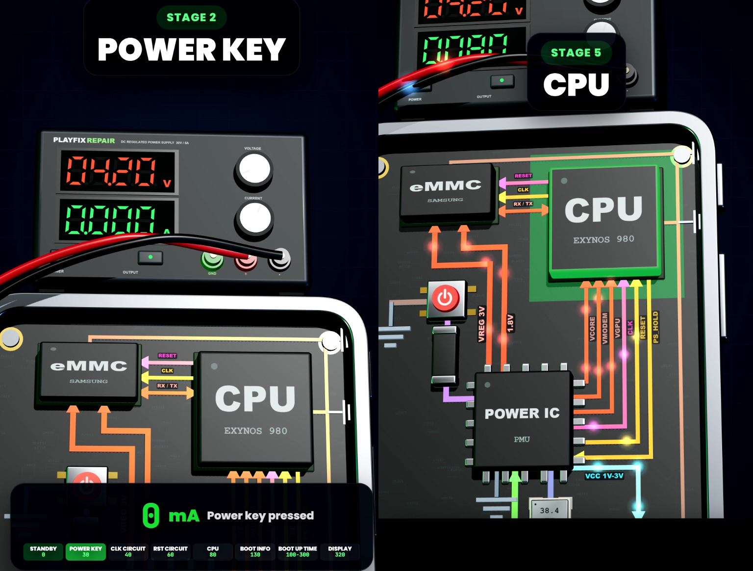
Learn how mobile-phone block diagrams connect ICs, power supplies, outputs and enable signals through clear 3D circuit animations.
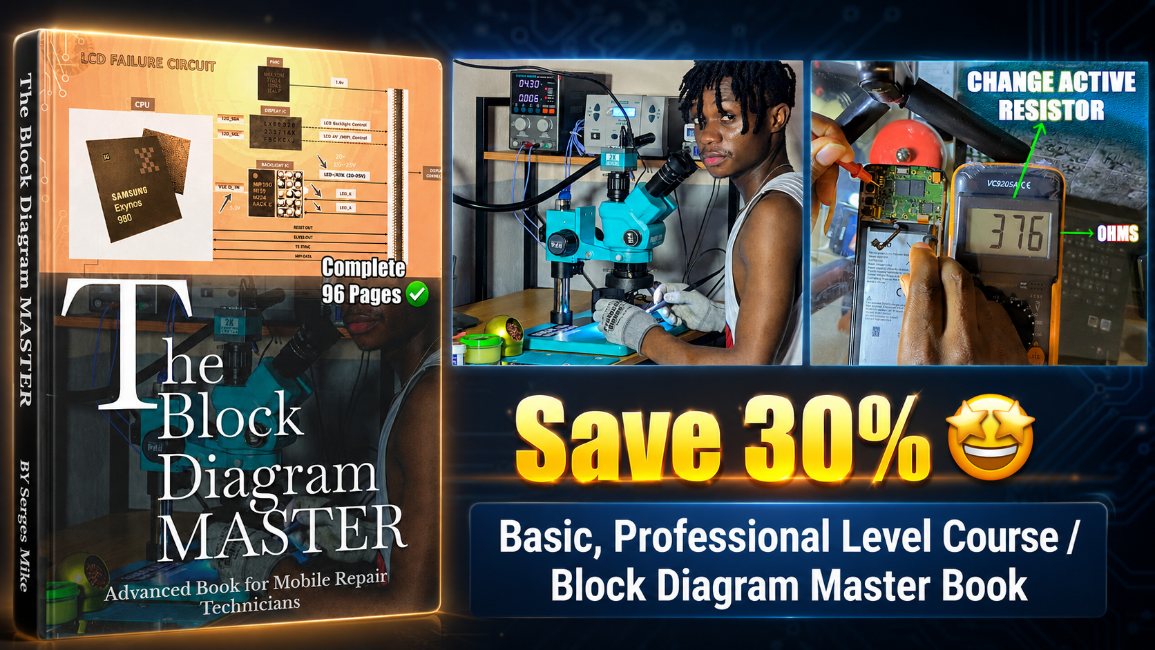
All PlayFix courses and the Block Diagram Master Book in one lifetime purchase.
Knowing how a phone powers on is the foundation of fast diagnosis: the battery and VPH, the power management IC, the main supply rails, the PS_HOLD signal and the CPU/RAM handshake. Block diagrams and schematics turn guessing into a step-by-step test plan.
Follow the power-on sequence on the block diagram. Identify the main supply rails and their sources. Use schematics to find test points for each line.